
Previously in this blog post series, I walked you through a bit of history of data centre networking and introduced Calico for Kubernetes. This blog post deep dives into setting up IP Fabric on Cumulus VX and spinning up Kubernetes cluster connected to it.
Scenarios that leverage this setup are described in parts three and four of this series.
All scripts and playbooks used in this blog post can be found in this repository, in case you want to bring the whole environment up on your own workstation.
Building a Test Data Centre Network Environment for Kubernetes
Cumulus VX
Building physical infrastructure can be a tedious and expensive task just for prototyping and testing. Luckily, at some point vendors decided to release virtual images of their networking devices (switches in this case) that can be run on almost any x86 workstation. They typically support various hypervisor platforms too.
This creates an opportunity to build and test network topologies without any piece of physical network hardware and address many concerns at the early stages of projects. You can consider using virtual appliances for building ad-hoc virtual replicas of your physical production infrastructure for testing changes, and embed this into your CI/CD pipeline.
One of the networking vendors that provides virtual images available for free download is Cumulus Networks. The Cumulus VX is a virtual appliance running Cumulus Linux as a network operating system and does packet forwarding in software.
Test Environment
The test environment will be provisioned with HashiCorp Vagrant, using VirtualBox as hypervisor. The Cumulus VX image will be used as a network switch. An Ansible playbook, available in the repository, is used to provision base network configuration. A set of Bash scripts are used to provision Kubernetes clusters. This scripts simply wrap the kubeadm, kubectl, and calicoctl commands.
The test environment network consists of two spine switches and two leaf switches. Each leaf switch is connected to two distinct spine switches. There is no spine-to-spine or leaf-to-leaf direct connection.
The IP routing protocol external BGP (eBGP) is used. This implies that each switch needs to have a different Autonomous System number (AS number) assigned. Here’s what the test environment’s network topology for IP Fabric with external BGP looks like:
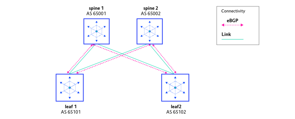
| Switch name | AS number |
| spine1 | AS 65001 |
| spine2 | AS 65002 |
| leaf1 | AS 65101 |
| leaf2 | AS 65102 |
Each leaf switch has several Kubernetes nodes connected to it. In this test environment there will be just one Kubernetes cluster, with a single master node provisioned together with four worker nodes. The complete test environment, with Kubernetes nodes, is presented on the diagram below.
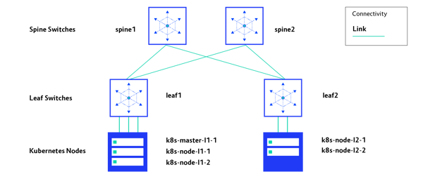
The code that is used to build the whole test environment can be grabbed from the GitLab repository.
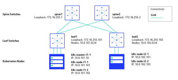
IP Addressing
Each IP Fabric switch has a unique IP address assigned to its loopback interface, and it is advertised to Border Gateway Protocol (BGP) for IP reachability testing. Each of the leaf switches has one directly connected network: 10.0.101.0/24 and 10.0.102.0/24, respectively. These networks are advertised via BGP to achieve Kubernetes nodes' full connectivity. IP addressing in the test environment is depicted here:
Bringing Network Components Up
In order to spin it up on your workstation, feel free to clone the GitLab repository. Follow the instructions in the README.md file.
IP Fabric Deployment with Vagrant and Ansible
We use vagrant needs to provision virtual machines running Cumulus VX as network switches. This can be done by executing the following command in the main folder of the cloned repository:
$ vagrant up leaf1 spine1 leaf2 spine2
After a few minutes, Vagrant should have provisioned four virtual machines running Cumulus VX. You can confirm that by executing the following command:
$ vagrant status
Current machine states:
spine1 running (virtualbox)
spine2 running (virtualbox)
leaf1 running (virtualbox)
leaf2 running (virtualbox)
k8s-master-l1-1 not created (virtualbox)
k8s-node-l1-1 not created (virtualbox)
k8s-node-l1-2 not created (virtualbox)
k8s-node-l2-1 not created (virtualbox)
k8s-node-l2-2 not created (virtualbox)
The next step is to configure the VMs using our Ansible playbook. For convenience, this is wrapped in the fabric.deploy.sh script, which can be executed as follows (full output is omitted for brevity).
$ sh fabric.deploy.sh
leaf-sw1 : ok=13 changed=11 unreachable=0 failed=0
leaf-sw2 : ok=13 changed=11 unreachable=0 failed=0
spine-sw1 : ok=10 changed=8 unreachable=0 failed=0
spine-sw2 : ok=10 changed=8 unreachable=0 failed=0
Configuration should be applied without any issues and you should receive output similar to the one above in result of playbook execution.
Basic IP Fabric Health Checks
Before moving on to Kubernetes networking and scenarios described further, it is worth checking the health of our network. The critical element of IP Fabric is the BGP routing protocol, so it is worth checking whether all BGP peerings were established.
Leaf1: BGP peerings
Leaf1 should successfully establish a session with spine1 and spine2.
$ vagrant ssh leaf1 -c "sudo net show bgp sum"
show bgp ipv4 unicast summary
=============================
BGP router identifier 172.16.255.101, local AS number 65101 vrf-id 0
BGP table version 6
RIB entries 11, using 1672 bytes of memory
Peers 2, using 39 KiB of memory
Peer groups 1, using 64 bytes of memory
Neighbor V AS MsgRcvd MsgSent TblVer InQ OutQ Up/Down State/PfxRcd>
spine-sw1.lab.local(172.16.0.0) 4 65001 139 140 0 0 0 00:06:37 3
spine-sw2.lab.local(172.16.0.4) 4 65002 139 140 0 0 0 00:06:37 3
Leaf2: BGP peerings
Leaf2 should successfully establish a session with spine1 and spine2.
$ vagrant ssh leaf2 -c "sudo net show bgp sum"
show bgp ipv4 unicast summary
=============================
BGP router identifier 172.16.255.102, local AS number 65102 vrf-id 0
BGP table version 6
RIB entries 11, using 1672 bytes of memory
Peers 2, using 39 KiB of memory
Peer groups 1, using 64 bytes of memory
Neighbor V AS MsgRcvd MsgSent TblVer InQ OutQ Up/Down State/PfxRcd
spine-sw1.lab.local(172.16.0.2) 4 65001 141 142 0 0 0 00:06:45 4
spine-sw2.lab.local(172.16.0.6) 4 65002 141 142 0 0 0 00:06:45 4
Spine1: BGP peerings
Spine1 should successfully establish a session with leaf1 and leaf2.
$ vagrant ssh spine1 -c "sudo net show bgp sum"
show bgp ipv4 unicast summary
=============================
BGP router identifier 172.16.255.1, local AS number 65001 vrf-id 0
BGP table version 6
RIB entries 11, using 1672 bytes of memory
Peers 2, using 39 KiB of memory
Neighbor V AS MsgRcvd MsgSent TblVer InQ OutQ Up/Down State/PfxRcd
leaf-sw1.lab.local(172.16.0.1) 4 65101 167 166 0 0 0 00:07:58 3
leaf-sw2.lab.local(172.16.0.3) 4 65102 167 166 0 0 0 00:07:58 3
Spine2: BGP peerings
Spine2 should successfully establish a session with leaf1 and leaf2.
$ vagrant ssh spine2 -c "sudo net show bgp sum"
show bgp ipv4 unicast summary
=============================
BGP router identifier 172.16.255.2, local AS number 65002 vrf-id 0
BGP table version 6
RIB entries 11, using 1672 bytes of memory
Peers 2, using 39 KiB of memory
Neighbor V AS MsgRcvd MsgSent TblVer InQ OutQ Up/Down State/PfxRcd
leaf-sw1.lab.local(172.16.0.5) 4 65101 169 168 0 0 0 00:08:05 5
leaf-sw2.lab.local(172.16.0.7) 4 65102 169 168 0 0 0 00:08:05 5
Leaf1: ping test
As it can be observed in the outputs above, all four instances of switches have successfully established their BGP peering with remote peers as planned. This means that the control plane of our network is operational.
We should now test the data plane, which is responsible for carrying traffic. The quickest way to validate IP reachability between switches is to issue a ping command sourced from IP of loopback interface of one switch and destined to IP addresses of loopbacks of the remaining switches.
In the example below, a ping test is issued from leaf1 switch and sourced from its IP 172.16.255.1 of loopback interface and targeted to loopback IP 172.16.255.1 of the spine1 switch.
$ vagrant ssh leaf1 -c "sudo ping 172.16.255.1 -I 172.16.255.101 -c 5"
PING 172.16.255.1 (172.16.255.1) from 172.16.255.101 : 56(84) bytes of data.
64 bytes from 172.16.255.1: icmp_seq=1 ttl=64 time=0.315 ms
64 bytes from 172.16.255.1: icmp_seq=2 ttl=64 time=0.514 ms
64 bytes from 172.16.255.1: icmp_seq=3 ttl=64 time=0.421 ms
64 bytes from 172.16.255.1: icmp_seq=4 ttl=64 time=0.563 ms
64 bytes from 172.16.255.1: icmp_seq=5 ttl=64 time=0.433 ms
$ vagrant ssh leaf1 -c "sudo ping 172.16.255.2 -I 172.16.255.101 -c 5"
PING 172.16.255.2 (172.16.255.2) from 172.16.255.101 : 56(84) bytes of data.
64 bytes from 172.16.255.2: icmp_seq=1 ttl=64 time=0.265 ms
64 bytes from 172.16.255.2: icmp_seq=2 ttl=64 time=0.582 ms
64 bytes from 172.16.255.2: icmp_seq=3 ttl=64 time=0.383 ms
64 bytes from 172.16.255.2: icmp_seq=4 ttl=64 time=0.507 ms
64 bytes from 172.16.255.2: icmp_seq=5 ttl=64 time=0.448 ms
$ vagrant ssh leaf1 -c "sudo ping 172.16.255.102 -I 172.16.255.101 -c 5"
PING 172.16.255.102 (172.16.255.102) from 172.16.255.101 : 56(84) bytes of data.
64 bytes from 172.16.255.102: icmp_seq=1 ttl=63 time=0.558 ms
64 bytes from 172.16.255.102: icmp_seq=2 ttl=63 time=0.867 ms
64 bytes from 172.16.255.102: icmp_seq=3 ttl=63 time=0.722 ms
64 bytes from 172.16.255.102: icmp_seq=4 ttl=63 time=0.822 ms
64 bytes from 172.16.255.102: icmp_seq=5 ttl=63 time=0.756 ms
As it can be observed in the ping test outputs, leaf1 switch is able to ping loopback IPs of the three remaining switches. This means that both the control and data plane of the test network is operational.
Verify BGP Routes on One of the Spine Switches
The Kubernetes nodes that we are about to deploy will be connected to leaf1 and leaf2, respectively. Nodes connected to leaf1 will have IPs from 10.0.101.0/24 network. Nodes connected to leaf2 will have IPs from 10.0.102.0/24 network. Leaf1 is advertising 10.0.101.0/24 to both spines via BGP. Leaf2 does the same with 10.0.102.0/24. Routes to these destinations are propagated across whole IP Fabric via BGP, so it is worth checking on one of the spine switches to see if these routes were received.
As you can see in the command output below, spine1 has received two routes pointing to the leaf1 and leaf2 networks, respectively.
$ vagrant ssh spine1 -c "sudo net show bgp"
show bgp ipv4 unicast
=====================
BGP table version is 6, local router ID is 172.16.255.1
Status codes: s suppressed, d damped, h history, * valid, > best, = multipath,
i internal, r RIB-failure, S Stale, R Removed
Origin codes: i - IGP, e - EGP, ? - incomplete

Network Next Hop Metric LocPrf Weight Path
*> 10.0.101.0/24 172.16.0.1 0 0 65101 ?
*> 10.0.102.0/24 172.16.0.3 0 0 65102 ?
[Output omitted for brevity]
Deploying a Kubernetes Cluster
Once IP Fabric is fully deployed, the next step is to provision VMs for Kubernetes and all scripts that will pre-configure all Kubernetes nodes. Issue the following command to bring the VMs up:
$ vagrant up k8s-master-l1-1 k8s-node-l1-1 k8s-node-l1-2 k8s-node-l2-1 k8s-node-l2-2
Verify the status of your VMs with the following command:
$ vagrant status
Current machine states:
spine1 running (virtualbox)
spine2 running (virtualbox)
leaf1 running (virtualbox)
leaf2 running (virtualbox)
k8s-master-l1-1 running (virtualbox)
k8s-node-l1-1 running (virtualbox)
k8s-node-l1-2 running (virtualbox)
k8s-node-l2-1 running (virtualbox)
k8s-node-l2-2 running (virtualbox)
Next, execute the following script to configure the IP address on each node, install packages , and tweak kernel settings required by Kubernetes per kubeadm documentation. In the last phase, the script will call kubeadm init to bring up the Kubernetes control plane of the cluster. We need to copy the token and cert digest from the output of kubeadm init command so we can use them later. (Output is omitted for brevity.)
$ sh vagrant.prepare_nodes.sh
Your Kubernetes control-plane has initialized successfully!
To start using your cluster, you need to run the following as a regular user:
mkdir -p $HOME/.kube
sudo cp -i /etc/kubernetes/admin.conf $HOME/.kube/config
sudo chown $(id -u):$(id -g) $HOME/.kube/config
You should now deploy a pod network to the cluster.
Run "kubectl apply -f [podnetwork].yaml" with one of the options listed at:
https://kubernetes.io/docs/concepts/cluster-administration/addons/
Then you can join any number of worker nodes by running the following on each as root:
kubeadm join 10.0.101.10:6443 --token 3wvck0.a3lqz6vgktx74gto \
--discovery-token-ca-cert-hash sha256:e3efc47abcbaa88c9e158936fcc88977df708c9b91cdff49dcf279ae48368154
Pass these parameters to vagrant.join_nodes.sh script in order to join worker nodes to the cluster.
$ sh vagrant.join_nodes.sh 3wvck0.a3lqz6vgktx74gto sha256:e3efc47abcbaa88c9e158936fcc88977df708c9b91cdff49dcf279ae48368154
Each of the nodes should successfully join the cluster. This can be confirmed with the following command:
$ vagrant ssh k8s-master-l1-1 -c "kubectl get nodes -o wide"
NAME STATUS ROLES AGE VERSION INTERNAL-IP EXTERNAL-IP OS-IMAGE KERNEL-VERSION CONTAINER-RUNTIME
k8s-master-l1-1 NotReady master 3m31s v1.15.2 10.0.101.10 <none> CentOS Linux 7 (Core) 3.10.0-957.12.2.el7.x86_64 docker://18.6.2
k8s-node-l1-1 NotReady <none> 89s v1.15.2 10.0.101.101 <none> CentOS Linux 7 (Core) 3.10.0-957.12.2.el7.x86_64 docker://18.6.2
k8s-node-l1-2 NotReady <none> 84s v1.15.2 10.0.101.102 <none> CentOS Linux 7 (Core) 3.10.0-957.12.2.el7.x86_64 docker://18.6.2
k8s-node-l2-1 NotReady <none> 78s v1.15.2 10.0.102.101 <none> CentOS Linux 7 (Core) 3.10.0-957.12.2.el7.x86_64 docker://18.6.2
k8s-node-l2-2 NotReady <none> 71s v1.15.2 10.0.102.102 <none> CentOS Linux 7 (Core) 3.10.0-957.12.2.el7.x86_64 docker://18.6.2
As it can be observed in the snippet above, all of the nodes in the cluster are in NotReady status. This expected and is due to the networking component not being deployed yet. Now, one of the two deployment scenarios must be selected.
See parts three and four of this series to learn about two scenarios for Kubernetes and Calico networking with IP Fabric.
We have our first-ever book coming: 'Cloud Native Transformation: Practical Patterns for Innovation'. Click below to pre-order now!